In Part 1 of this series, I showed how to begin the park pergola design, by modeling the curved horizontal beam that follows the pergola path.
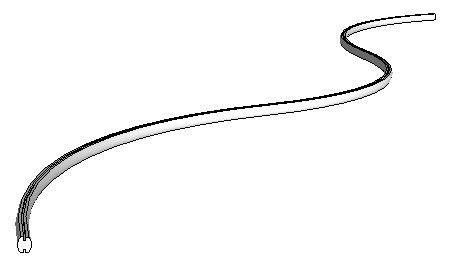
In this post, I’ll show how to model the vertical supports for the beam.
Design One Support
Draw the cross section of the support like this: 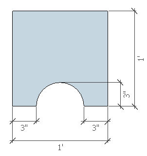
The extension I used for this part is Fredoscale. But it would also be easy to change the cross-section with SketchUp’s native tools.
Select the cross-section face, and activate the Taper tool of FredoScale. Taper the top edge of the face by about 50%. 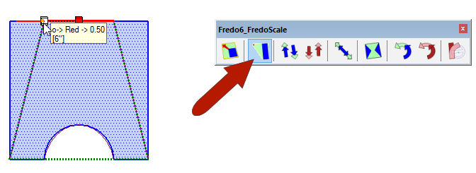
Pull up the support to a 12′ height. Select and make it a component. But before clicking Create, note the axes of the component. The component origin should be at the bottom of the support, as shown below. But what’s also important is the axes orientation. For the Path Copy extension to place these supports correctly along the pergola path, the green axis of the component should be perpendicular to the path; the red axis of the component should go along the path. That’s how my component below is set up, so I’m good to go. Click Create. 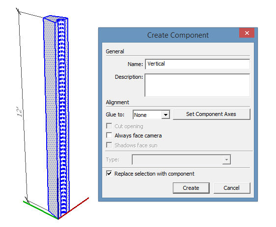
But before arraying these along the path, open the component for editing, and use the Rotate tool to rotate it back just a little – about 15 degrees. Then close the component. 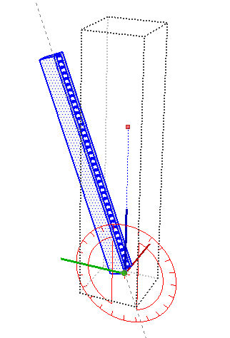
Copy Along the Path
Here’s where I use the Path Copy extension.
Move the curved beam into blank space, so that the arcs that form the pergola path are visible.
Select one of the outer arcs and activate Path Copy (found in the Extensions menu). Then click the support component. 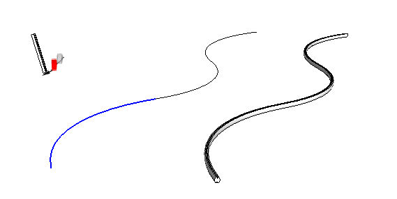
Enter your support spacing (I’m using 10 feet). You should now have several supports along the arc, at the spacing you want.
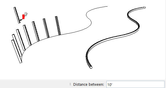
Do the same support layout for the other outer arc.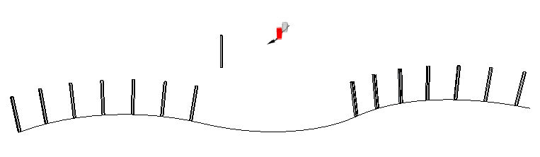
Erase the first and last supports.
Now carefully move the beam up to sit atop the supports. You’ll have to do some fine-tuning to get the placement just right. 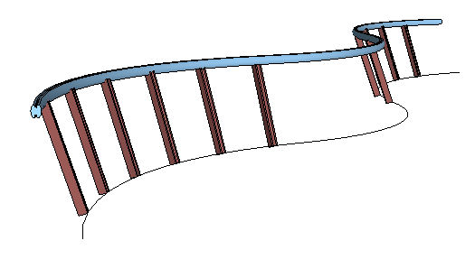
Coming next, in Part 3, I’ll finish up the pergola by adding a set of tilted cross-beams.
